
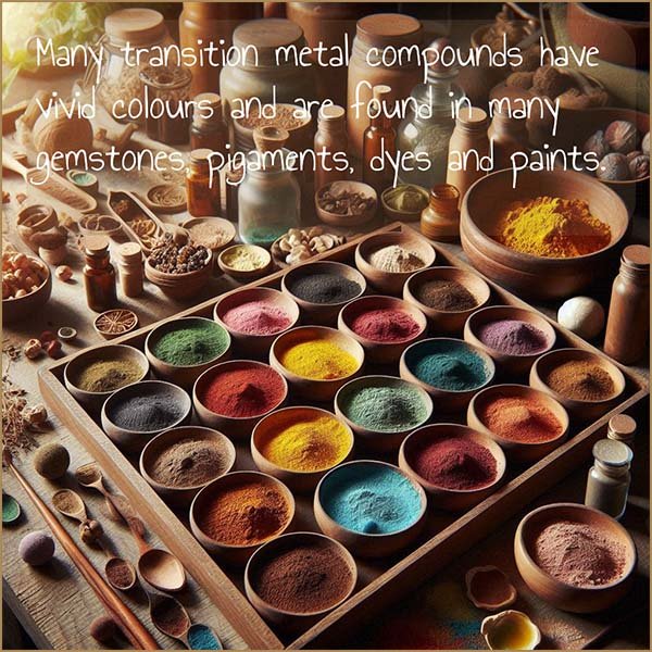
Many transition metal compounds have very vivid and beautiful colours. These coloured compounds can be found in:
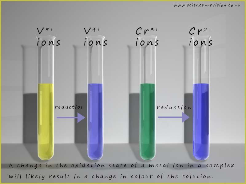
Changing the oxidation state of the metal ion present in a solution will also likely result in a colour change; for example the image below shows the colour changes when the transition metal vanadium in the +5 oxidation state is reduced to form vanadium (IV) ions (V+4) and also the colour change that occurs when a solution containing Cr3+ ions -[Cr(H2O)6]3+ is reduced to form Cr2+ ions -[Cr(H2O)6]3+.
As further example on how changing the oxidation state of the metal ion results in a colour change consider the oxidation of the iron(II) ion-(Fe2+) in the hexaaquairon(II) complex to form the iron(III) ion- (Fe3+) hexaaqua complex ion , this results in the solution changing colour from a green colour to a pale yellow/orange coloured solution, an equation for this oxidation reaction is shown below:
As we have seen above the colour of a transition metal complex can be changed by:
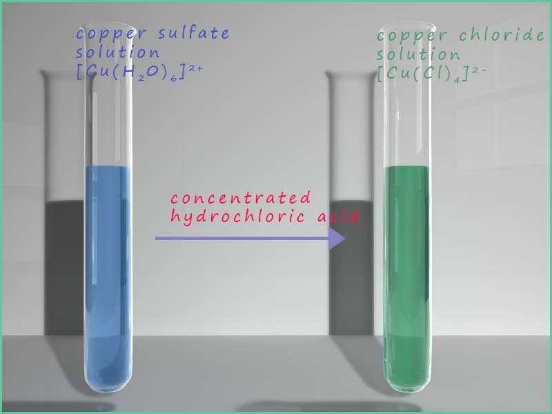
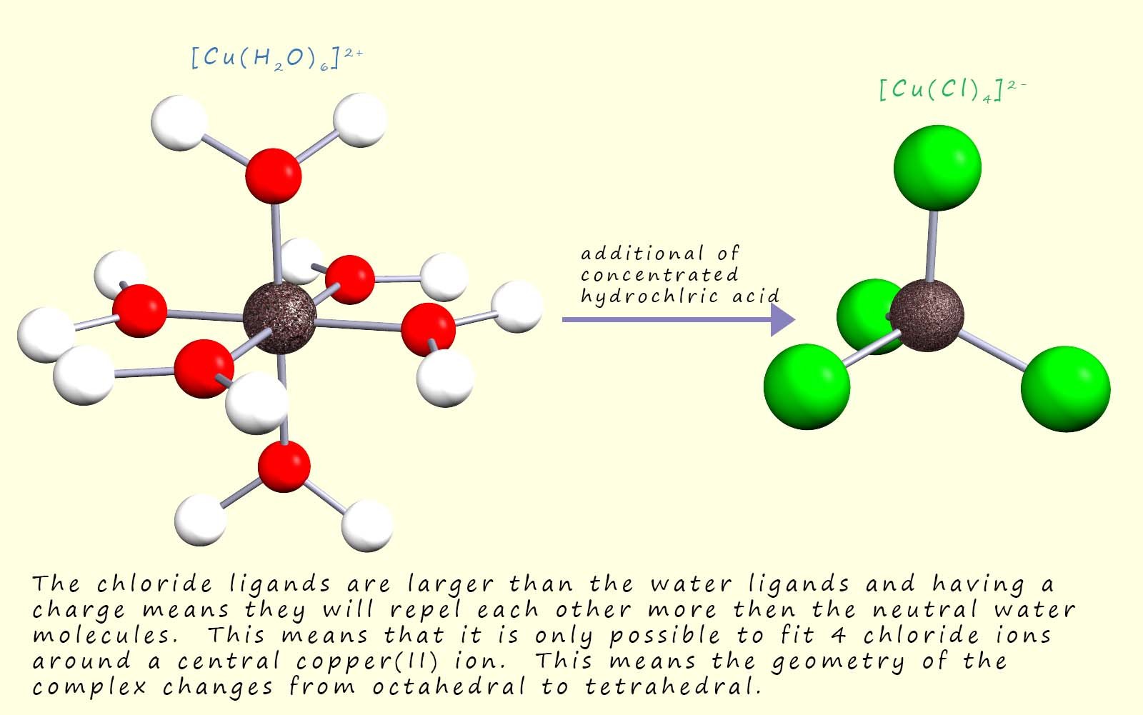
The chloride ions (Cl-) ions are larger than the water ligands present in hexaaquacopper(II) complex present in the copper sulfate solution and being charged means there will be more repulsion between the chloride ligands than the neutral water ligands, these two factors help to reduce the coordination number from six to four as the complex changes from an octahedral complex to a tetrahedral one; this is shown in the image below:
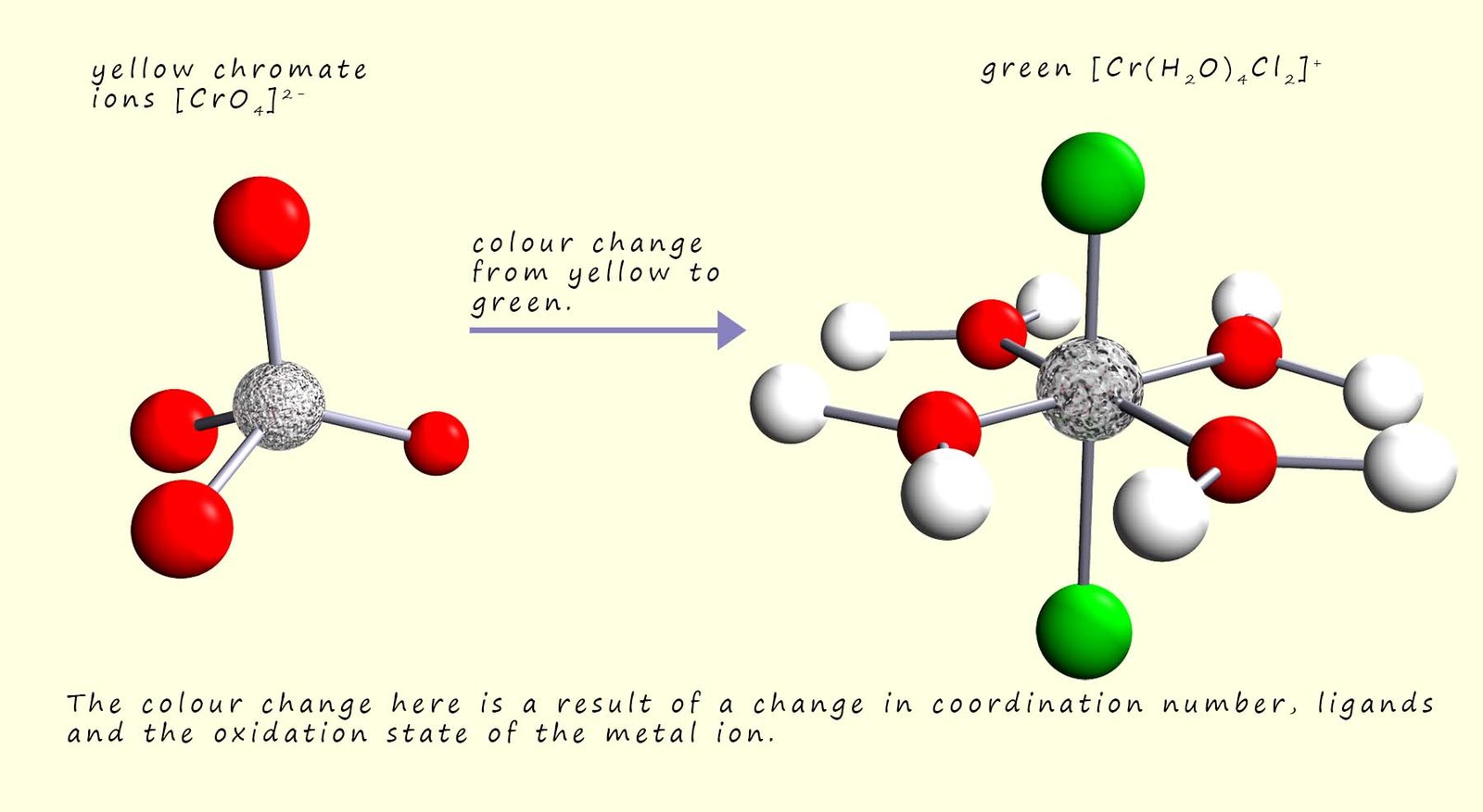
Although in some reactions the colour change may be as a result of all three factors changing, that is a change of ligand, coordination number and the oxidation state of the metal; as shown in the image below:
So why are many transition metal complexes coloured and why does changing the ligands or the metal present change the colour of these complexes? You may recall that when an electron inside an atom absorbs electromagnetic radiation with the correct frequency it can be promoted from a lower ground state to a higher or excited state or energy level, this was the basis of absorption spectra which you will no doubt have met previously.
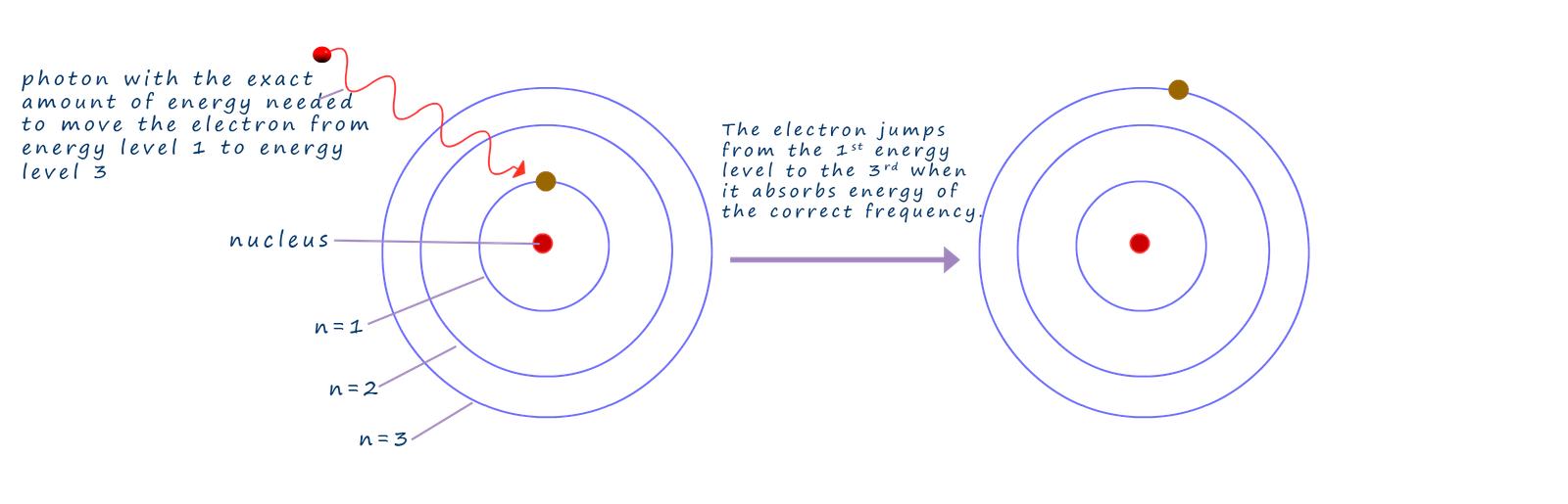
In the image below a photon of electromagnetic radiation is absorbed by an electron in the first principal level of an atom and this photon contains the exact amount of energy needed to promote the electron from the first principal energy level to the third principal energy level, now the promoted electron will quickly lose this energy and it will quickly drop back down to the ground state energy level and the same amount of energy that was needed to promote it will be given back out.
Now it just so happens that the wavelength (λ) of electromagnetic radiation absorbed by a transition metal when an electron moves from one energy level to another falls in the visible part of the electromagnetic spectrum, now the amount of energy lost or gained by an electron as it moves from one energy level inside the atom can be found using the Planck equation shown below:
Energy = Planck's constant x frequency
E = h x ν
Here E represents the energy of a single photon needed to promote an electron or the energy released when an excited electron drops back down to its original ground state; h is Planck's constant which has a value of 6.63 x 10⁻³⁴Js and the Greek symbol nu (ν) represents the frequency of the emitted radiation. From the Planck equation we can see that the higher the frequency of the electromagnetic radiation emitted or absorbed by the atom the more energy it will emit or absorb.
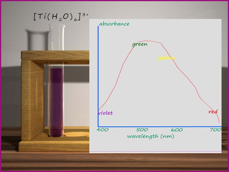
The amount of light or electromagnetic radiation absorbed by a substance is called absorbance and if we plot a graph of absorbance against wavelength (λ)
then an absorption spectrum is obtained. The image opposite shows an absorption spectrum for a solution of the hexaaqua titanium(III) complex [Ti(H2O6]3+, if you study the graph shown you will see that the complex absorbs wavelengths of electromagnetic radiation strongly in the green and yellow regions of the visible spectrum, the wavelengths (λ) of visible light corresponding to violet and red light are not absorbed well.
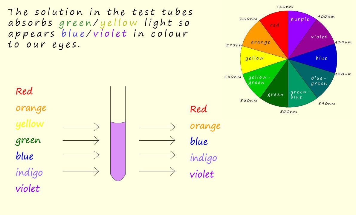
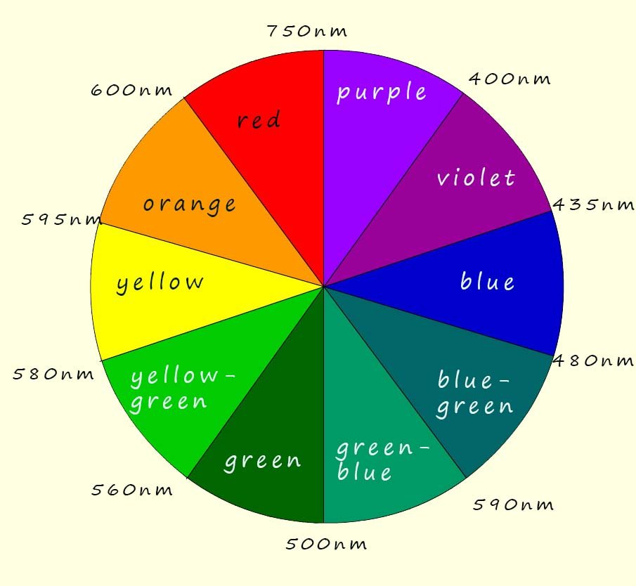 We can use a simple colour wheel (shown below) to predict the colour of any particular complex from its absorption spectrum, for example observed and complementary colours are usually directly opposite each other in the colour wheel, so for example if a solution absorbs orange light it will appear blueish/green and if a solution absorbs violet light it will appear yellow. So in our example the titanium solution is absorbing light in the yellow/green region of the visible spectrum so it appears violet/red. The colour of light that "we see" is the complementary colour of the absorbed light.
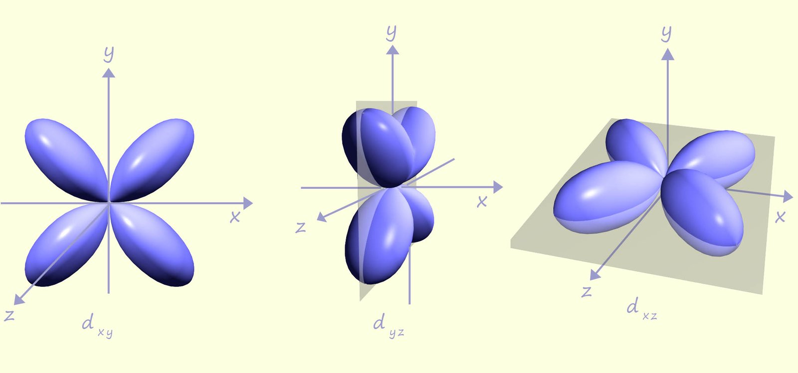
To better explain why transition metal ions form coloured salts and solutions we need to consider how the ligands present in a complex interact with the metal ion and in particular the d-orbitals present in the metal ion. Crystal field theory provides an explanation for the colour found in many of these complexes. Now let's just remind ourselves about the shape of the five d-orbitals. Three of the d-orbitals; the dxy, dxz and the dyz have lobes that complementary lie between the x, y and z axes as shown in the image below:
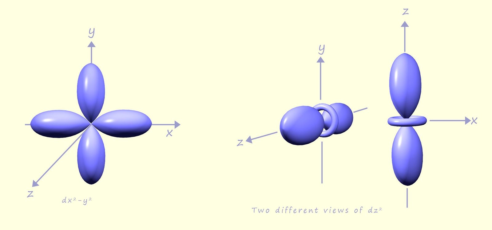
While the other two d-orbitals; the dx2-y2 and the dz2 have lobes that point directly along the x, y and z axes; as shown in the image below:
 Now consider the transition metal complex hexaaquatitanium(III); [Ti(H2O)]3+, this complex consists of a central titanium ion with a 3+ charge (Ti3+) surrounded by six water molecules or ligands, the complex has an octahedral shape as shown in the image opposite.
.jpg) In any transition metal atom or ion the five d-orbitals are all degenerate, that is they all have the same energy.
In any transition metal atom or ion the five d-orbitals are all degenerate, that is they all have the same energy.
However when the ligands approach and bond with the central transition metal ion the lone pair of electrons which the ligands use to form coordinate bonds to the central metal atom/ion will repel any electrons present in the d-orbitals. Now the ligands will approach the metal ion along the x, y and z axes, we know this simply because of the octahedral shape of the complex; where it is easy to imagine each of the ligands approaching the metal ion along these axes. However as the ligands approach the metal ion the repulsion from the electrons in the d-orbitals and electrons in the lone pairs of the ligands will raise the energies of all the d-orbitals, but not equally. The dx2-y2 and dz2 which lie along the x, y and z axes and point directly at the approaching ligands are raised more than the other three d-orbitals which point between the ligands, this splitting of the degeneracy of the d-orbitals is highlighted in the diagram below:
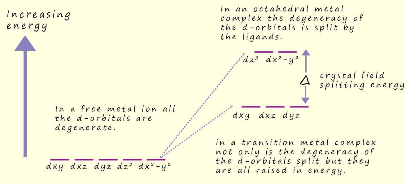
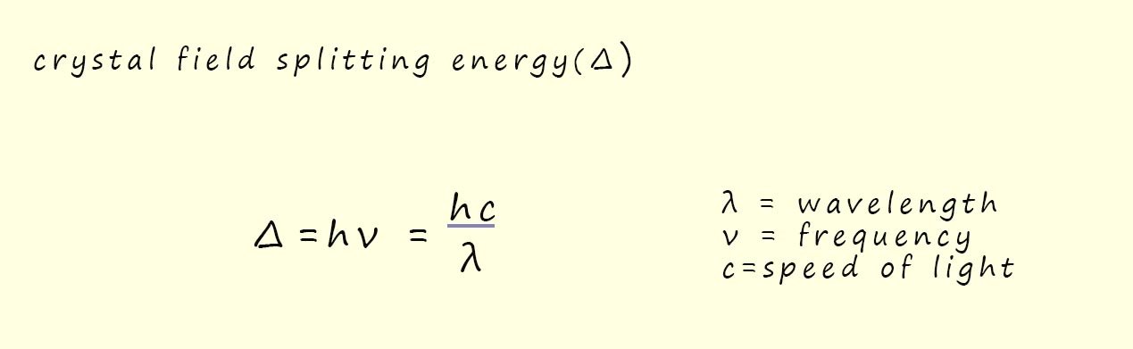
This splitting of the degeneracy of the d-orbitals is called the crystal field splitting energy(Δ) and its energy value usually corresponds to a wavelength of light in the visible part of the spectrum. Now it is likely that an electron in the lower set of d-orbitals can absorb a photon of visible light and be promoted into one of the higher energy d-orbitals, this transition of one or more electrons from the lower set of d-orbitals to the higher set is what is responsible for giving transition metal complexes their characteristic colours, since the wavelength of light that will be absorbed to enable these electron transitions all occur in the visible region of the spectrum.
Imagine white light, which consists of all the colours of the visible spectrum (red, orange, yellow, green, blue, indigo and violet) being passed through a solution of a transition metal complex, now the image below shows white light passing through a solution containing a transition metal compound, this solution absorbs green/yellow light. The light that passes through the solution, that is the light that is NOT absorbed is the light our eyes will see, that is white light minus the yellow/green colours which will appear violet/blue to our eyes. Simply use the colour wheel shown in the image to predict the colour of the solution, recall that the complementary colours of yellow and green are blue and violet (note that the complementary colours in light are not the same as those in paints).
Now it is relatively easy to calculate the value of the crystal field splitting energy (Δ) using Planck's equation, this is outlined below:
In the example above using the Ti3+ ion present in the octahedral complex Ti(H2O)63+, now this Ti3+ ion has only 1 electron in the d-orbitals and from the absorption spectrum shown above it has a strong absorption of light with a wavelength of 495nm. Now to work out the value of the crystal field splitting energy for this particular ion we have:
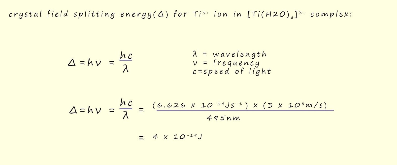
The calculated value of 4 x 10-19J is the energy required to promote a single electron from the low energy d-orbitals; often referred to as the t2g set of orbitals to the higher energy d-orbital; often referred to as the eg set of orbitals, to express this value in kJ per mole simply multiply by the Avogadro constant (6.02 x 10²³) and we obtain a crystal field splitting energy of 242kJmol-1.
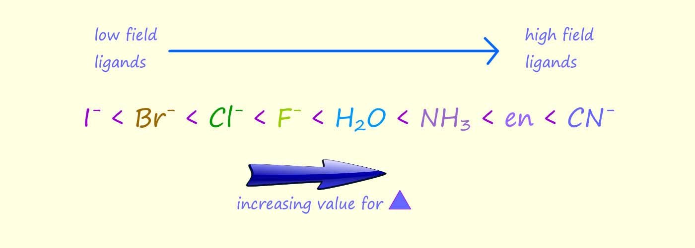
The size of the crystal field splitting energy depends on the metal and its oxidation state as well as the ligands present in the complex or coordination compound; for example the image below shows the crystal field splitting pattern for a series of complexes which all contain the chromium(III) ion (Cr3+) but this ion is bonded to different ligands. You can see that the cyanide (CN-) is able to split the d-orbitals much more than the fluoride ion (F-), this means that it will take more energy to promote an electron from the t2g set of d-orbitals to the higher eg set of d-orbitals or another way of putting this is the cyanide ligands have larger crystal field splitting energy (Δ).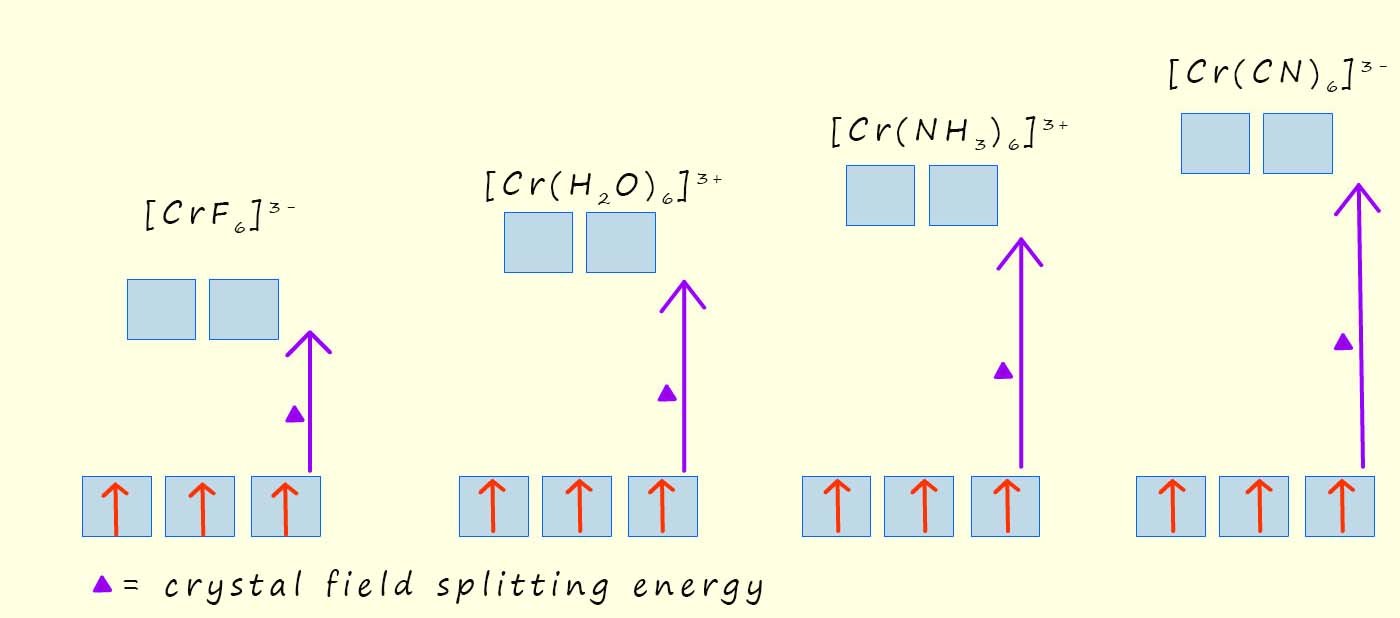 The spectrochemical series is a list which ranks the ability of ligands to split the crystal field. Ligands which give a relatively small value for the crystal field splitting energy (Δ), are called weak field ligands while ligands which give large values for the crystal field splitting energy (Δ) are called high field ligands|; part of the spectrochemical series showing some common ligands is listed below:
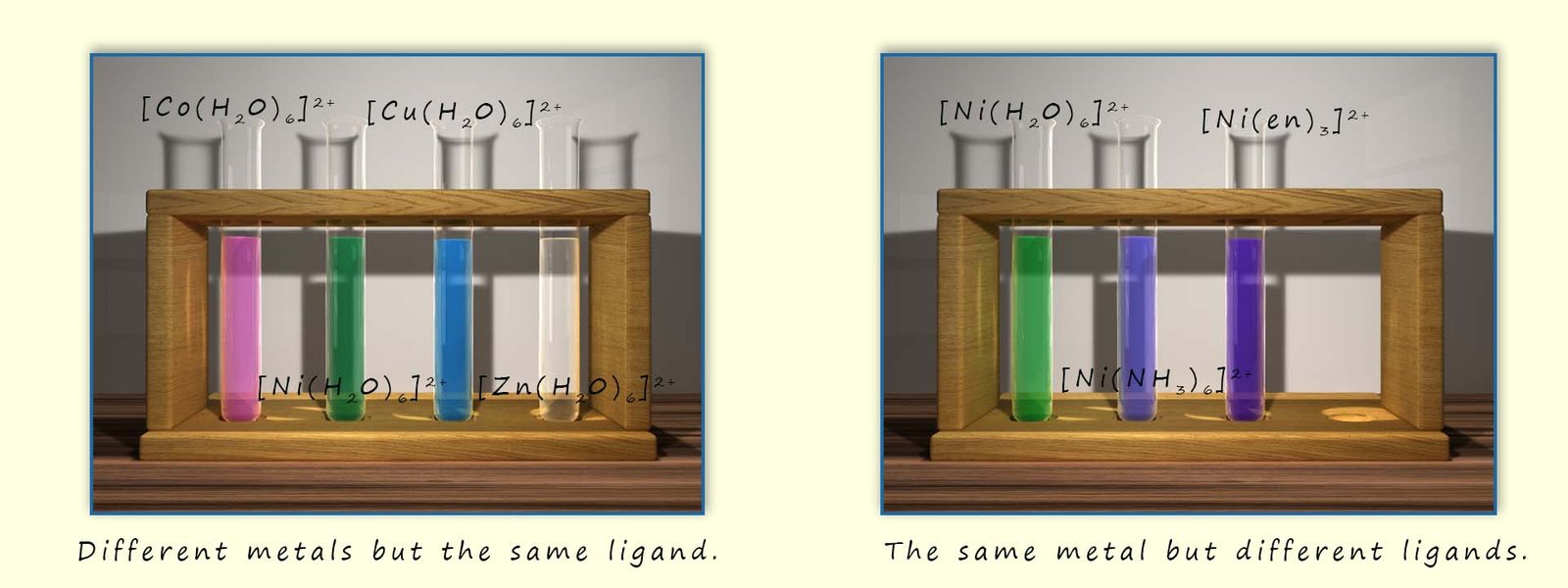
Different metal ions also have different values for the crystal field splitting energy (Δ) which explain why complexes containing different metal ions but the same ligands have different colours.
Changing the oxidation state of a metal ion means changing the number of d electrons present; for example Fe2+ has a d6 configuration while Fe3+ has a d5configuration. This difference in the number of d electrons directly impacts how these electrons interact with the ligands. The oxidation state of the metal ion in a complex affects the magnitude of the crystal field splitting energy (Δ), a higher oxidation state generally means a larger positive charge on the metal ion, this increased charge will therefore increase the electrostatic attraction between the metal ion and the negatively charged ligands or the negative ends of polar ligands which in turn will decrease the metal-ligand bond length and bring the ligands closer to the metal ion, now both of these factors increase the repulsion between the d electrons and the ligand electrons, leading to a larger crystal field splitting energy (Δ).
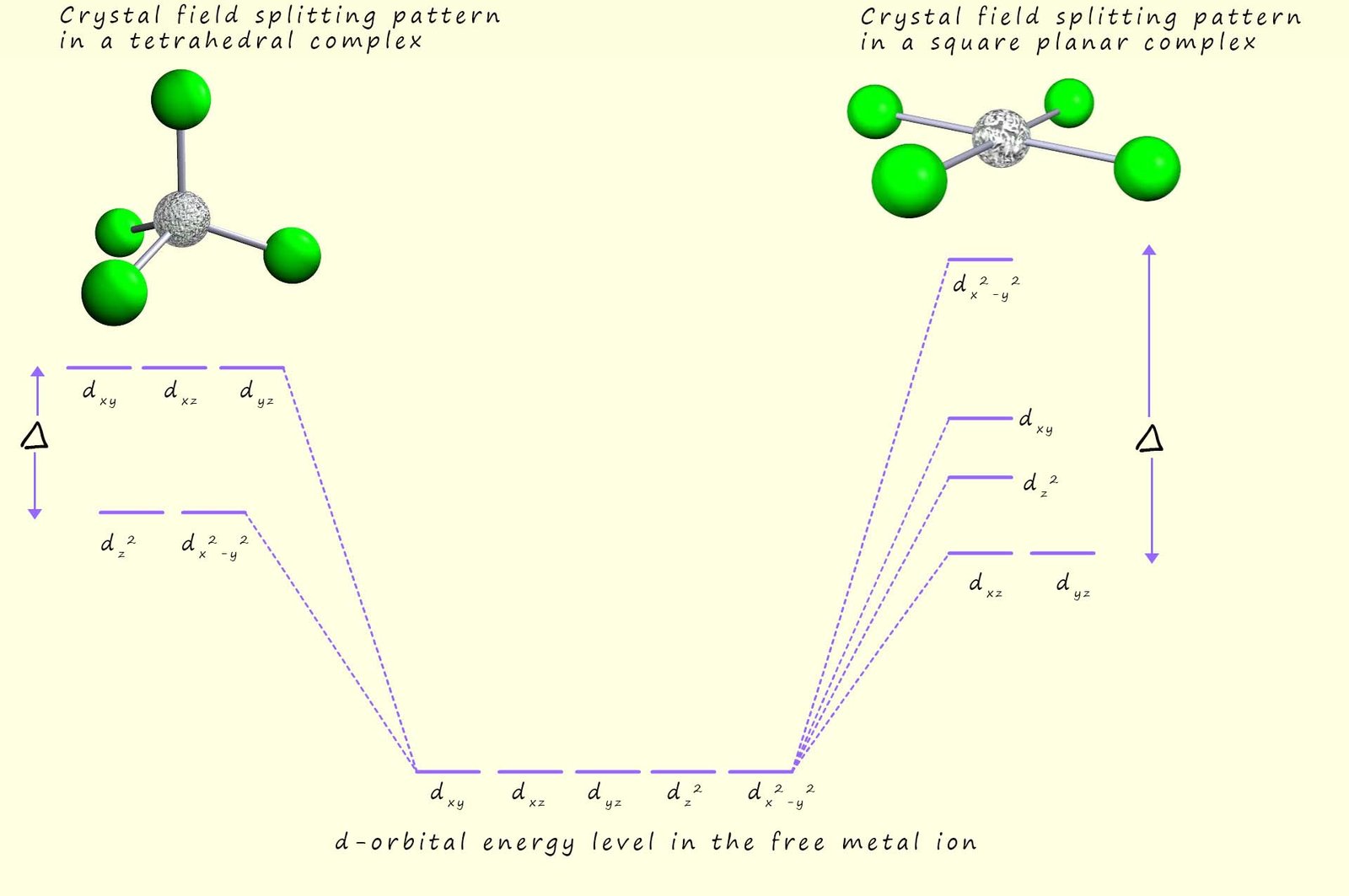
In a tetrahedral complex none of the bonded ligands point directly at the d-orbitals and since there are only 4 ligands present and not the six found in octahedral complexes the crystal field splitting energy in a tetrahedral complex is much less than that found in octahedral complexes. The splitting of the d-orbitals in a tetrahedral complex is also the opposite way round from that found in an octahedral complex; with the dxy, dyz and the dxz being lower in energy than the dx2-y2 and dz2 orbitals, this is outlined in the image below.
In a square planar complex the dx2-y2 orbital is higher in energy than the other d-orbitals since it points directly at the bonded ligands while the energy of the remaining d-orbitals is split as shown in the image below:
We have seen above that there are a number of factors that will affect the colour of transition metal complexes, these include for example: